No air-cooling retrofit trap
Built natively for high-density liquid-cooled clusters, without legacy constraints or downtime-heavy upgrades.
- Liquid-ready from day one
- Overhead services sized for density
- No stranded legacy floor
A native high-density baseline: hot-water liquid cooling, 800V DC distribution and redundant paths from the generation plant to the GPU.
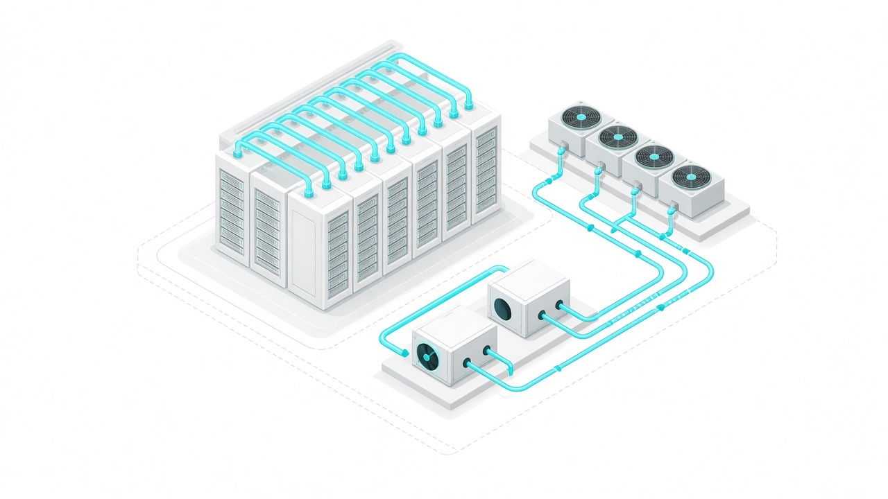
Conventional 10–20kW rooms cannot host 40kW+ accelerator racks without long, costly retrofits. These halls skip that step.
Built natively for high-density liquid-cooled clusters, without legacy constraints or downtime-heavy upgrades.
136kW per rack, 72 GPUs and 800G InfiniBand, with power and liquid distribution pre-installed.
Building and M&E natively support 230kW fanless racks at 45°C, with pipe capacity reserved for 600kW Kyber.
Cold plates take 80–100% of the heat straight off the silicon. Water leaves the CDU at 45°C, so dry coolers handle most of the rejection without chillers, even in a tropical climate.
Each rack has independent A and B supply and return loops for concurrent maintenance.
A single coordinated chain matched to next-generation GPU power specs, with fewer conversion steps and less copper.
Down from about 5% with conventional AC distribution.
Busbar current falls to 1,500A at 800V DC.
Silicon-carbide SSTs at over 97% efficiency.
Absorbs millisecond AI training load steps on the island grid.
Three forward-looking pillars prepare the campus for ESG audits and gigawatt-scale efficiency.
Rooftop and ground PV with 20MW/40MWh batteries for peak shaving and stable islanded operation.
International renewable energy certificates for hyperscaler ESG and carbon-neutral reporting.
Interfaces reserved beyond 1GW for seawater air conditioning, targeting near-zero freshwater use.
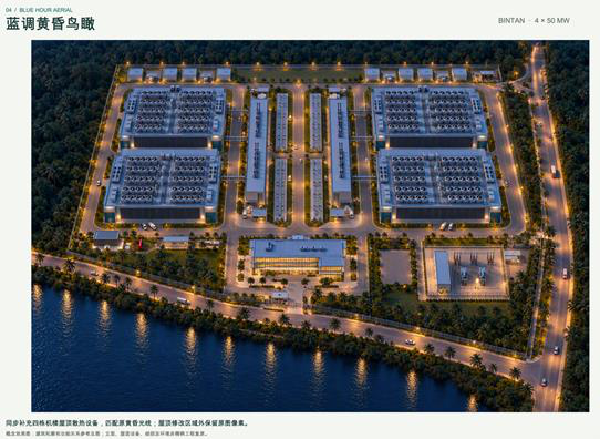
Our team will map your power density, cooling interface and network fabric to the hall design.